
ACL - Solenoid Valve Solutions
Solenoid Valve Solutions
ACL - Your gateway to excellence
ACL S.r.l. is manufacturing a wide range of solenoid valves in different versions since 1987.
Being focused on the satisfaction of customers’ needs, ACL is available to deal with all kind of requests concerning both standard and special products.
ACL’s expertise is testified by the large number of customers worldwide, which are acting in all the industrial fields where the control of fluid is necessary.
Quality
The high quality of the raw materials used, the precision of the parts, the hard tests carried out during manufacturing process and final testing, together with the large monthly quantity of valves produced are a guarantee of reliability.
Experience
ACL’s valves are employed in a large variety of industrial sectors: water treatment, electrical appliances, industrial process, heating and air-conditioning, medical equipment, automotive, textile, food, pneumatic and many others.
A worldwide sales network allows ACL to be present in the solenoid valve markets of the most important Countries.
ACL Construction details
The most important components of the solenoid valve are:
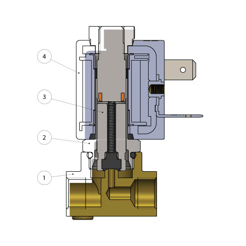
The most important components of the solenoid valve are:
Solenoid valves are equipment used to control media in pressure. Their action is to either open or close the interception device, directly or indirectly, when the coil is energized.
- 1. The body valve, which has an inlet and an outlet connection and an orifice for media flowing.
- 2. The armature tube, with the core, where the coil is fitted.
- 3. The plunger, which in some cases serves like a seal, sliding in the armature tube.
- 4. The coil, which produces the magnetic field required to move the plunger.
Various functions of the solenoid valve
2-way direct acting
2/2 way direct acting solenoid valves in both normally closed (NC) and normally open (NO) versions operate from a differential pressure of 0 bar. A 2/2 way valve has two connections and two switch positions. When energizing the coil, the valve will switch from one switch position to the other switch position.
2 way direct-acting | Normally closed
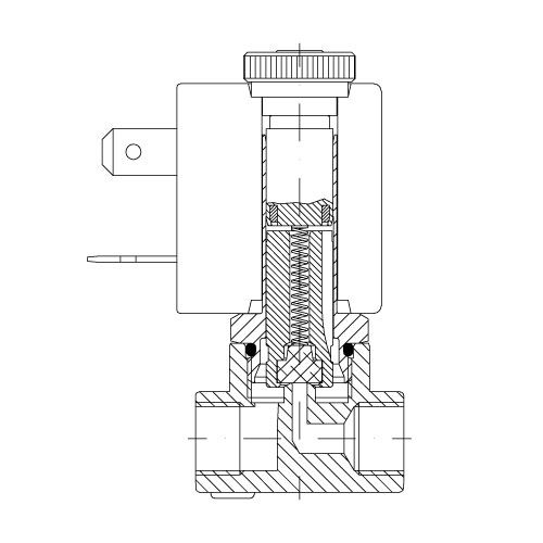
2 way direct-acting | Normally closed
The 2 way solenoid valve has an inlet and an outlet connection within the valve body. It can be normally closed (2/2 NC).
In this case the media is prevented from flowing through the orifice by the plunger seal.
When connected to an electrical supply, the orifice opens allowing the inlet to feed the outlet port.
2 way direct-acting | Normally open
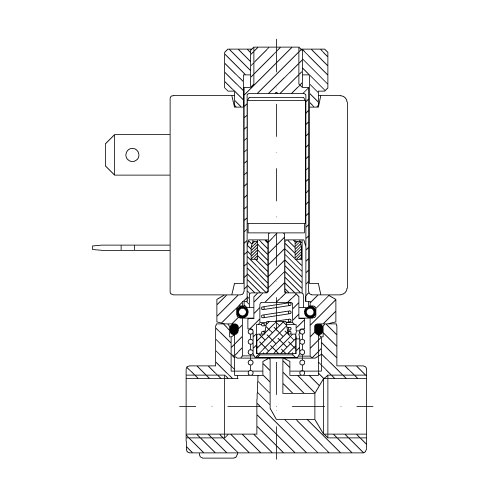
2 way direct-acting | Normally open
It can be normally open (2/2 NO). In this case the orifice is open, the inlet feeds through the outlet. When connected to an electrical supply the orifice is closed.
The operation, in both cases depends only on the magnetic field produced by the coil. These solenoid valves are able to work at zero pressure.
3-way direct acting
3/2 way direct acting solenoid valves in both normally closed (NC) and normally open (NO) versions operate from a differential pressure of 0 bar. A 3/2 way valve has three connections and two switch positions. When energizing the coil, the valve will switch from one switch position to the other switch position.
3 way direct-acting | Normally closed
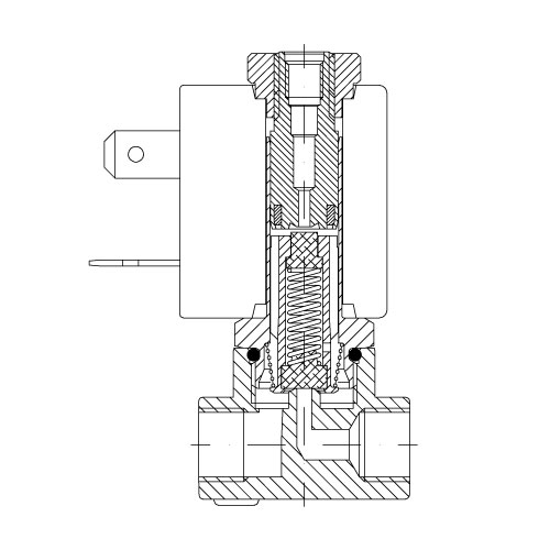
3 way direct-acting | Normally closed
The 3 way solenoid valve has inlet and outlet connections in the body and an exhaust connection above the core. It can be normally closed (3/2 NC).
In this case the media is prevented from flowing through the inlet orifice by the plunger seal. The inlet and exhaust orifices are at each end of the plunger. When connected to an electrical supply, the inlet orifice opens feed- ing the user port. The exhaust is closed.
3 way direct-acting | Normally open
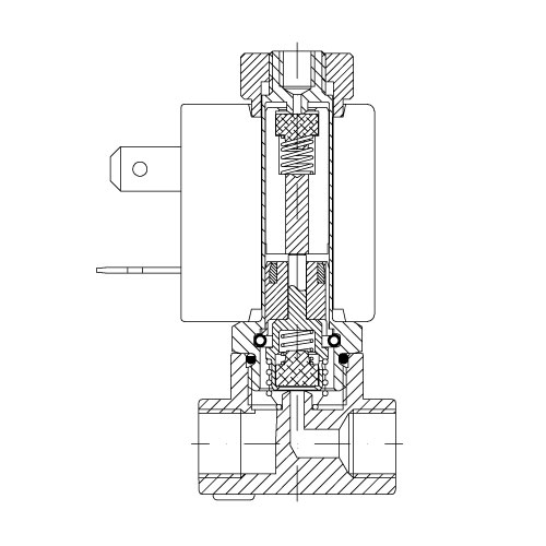
3 way direct-acting | Normally open
It can be normally open (3/2 NO). In this case when the coil isn’t energized the inlet orifice is open to the user port.
Exhaust port is closed. When connected to an electrical supply, the inlet orifice closes, at the same time the exhaust port is opened and con- nected with the user port. In both cases, the operation depends only on the magnetic field produced by the coil.
These solenoid valves are able to work at zero pressure.
Servo-assisted acting | Normally closed
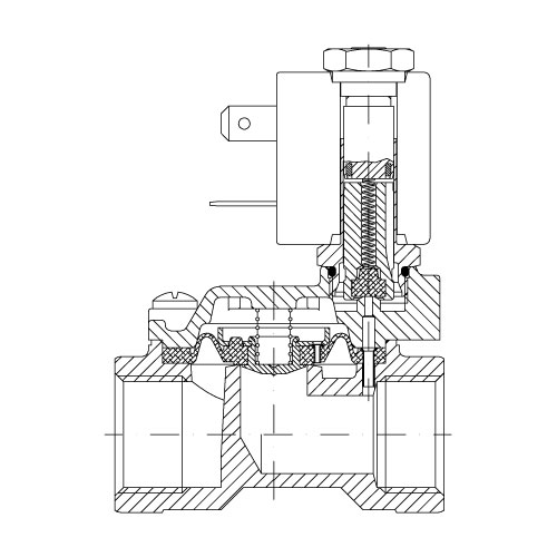
Servo-assisted acting | Normally closed
With larger orifices, static pressure increases, and it’s still necessary that the magnetic field produced by the coil is able to control these forces. This is achieved by using servo-assisted action in the solenoid valve.
In this design the media pressure helps to keep the main valve seal closed.
The normally closed design (2/2 NC) has an inlet and outlet connection in the valve body. When the coil is not energized, the flow is blocked by the main seal, which could be either a diaphragm or a piston design.
In this mode the medium flows through a small hole in the diaphragm or
piston and helps to close the valve. When the coil is energized the pilot
orifice opens, allowing the medium above the main seal to exhaust and the main valve
seal to open.
This type of solenoid valve needs a minimum differential pressure to work.
Servo-assisted acting | Normally open
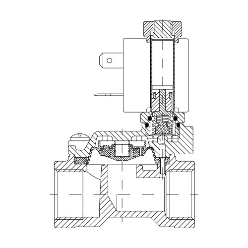
Servo-assisted acting | Normally open
The normally open (2/2 NO) version has an inlet and outlet connection in the valve body. With larger orifices, static pressure increases, and it’s still necessary that the magnetic field produced by the coil is able to control these forces. This is achieved by using servo-assisted action in the solenoid valve.
In this design the media pressure helps to keep the main valve seal open. When the coil isn’t energi zed, the flow is not interrupted by the main seal, which could be either a diaphragm or a piston design.
In this mode the medium flows through a small hole in the diaphragm or piston and helps the valve to open. When the coil is energized the pilot orifice closes, allowing the medium above the main seal to pressurize and the main valve seal to close.
This type of solenoid valve needs a minimum differential pressure to work.
Assisted-Lift diaphragm
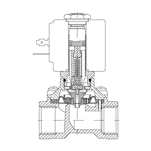
Assisted-Lift diaphragm
They are available with an assisted lift design pilot operated by diaphragm and normally closed (2/2 NC).
In these models the plunger is mechanically attached to the diaphragm and controls the central pilot orifice and the stroke of the main seal.
This design allows the valve to work at zero differential pressure.
Angle seat valves
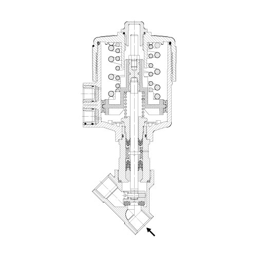
Angle seat valves
his type of valve is controlled by a pilot fluid supplied to the actuator by means of a pilot valve.
The control part of the valve (pneumatic actuator) is connected to the body valve by a stem. The main orifice is closed by a poppet that includes the main seat. The pressurizing of the main actuator of the valve opens the flow of the fluid.
These valves are mainly suitable for contaminated or extremely viscous process
fluids.
Seal Materials
Designation | Commercial denomination | General characteristics | Typical applications |
NBR | BUNA -N | A synthetic elastomer with good mechanical and thermal properties. | Water (max T=+70°C) Air (max T=+90°C) |
EPDM | BUNA- | A synthetic elastomer derived from the co-polymerization of ethylene and propylene. | Hot water and steam. Detergents. |
FPM (Fluorocarbon) | VITON | A synthetic elastomer derived from flour-propylene. | For general use up to +140°C |
PTFE | TEFLON | Thermoplastic material used also filled with a mineral resin. | For general use up to +180°C |
Media Compatability
The following table has the scope to provide an indication of the general characteristics with regards to the compatibility with the different materials and media.
To determine the compatibility with corrosive fluids it is important to know all the data relative to : temperature, concentration and media composition.
Media | Brass | Stainless steel | NBR | EPDM | FPM | PTFE |
Acetone | Yes | Yes | No | Yes | No | Yes |
Acetylene | Yes | Yes | No | Yes | Yes | Yes |
Argon Hold | Yes | Yes | No | Yes | Yes | Yes |
Benzol | Yes | Yes | No | No | No | Yes |
Butane | Yes | Yes | No | No | Yes | Yes |
Calcium monoxide | Yes | Yes | Yes | Yes | Yes | Yes |
Carbon dioxide (liquid) | No | Yes | No | No | No | Yes |
Carbon disulphide | Yes | Yes | No | No | No | Yes |
Chloroform | Yes | Yes | No | No | No | Yes |
De-ionised water | No | Yes | Yes | Yes | Yes | Yes |
De mineralised water | No | Yes | Yes | Yes | Yes | Yes |
Dry carbon dioxide (gas) | Yes | Yes | Yes | Yes | Yes | Yes |
Ethane | Yes | Yes | Yes | No | Yes | Yes |
Ethanol | Yes | Yes | No | No | No | Yes |
Ethyl acetate | Yes | Yes | No | No | No | Yes |
Ethyl cloride | Yes | Yes | Yes | Yes | Yes | Yes |
Ethyl glycol | Yes | Yes | Yes | Yes | Yes | Yes |
Formeldehyde | Yes | Yes | Yes | Yes | Yes | Yes |
Freon | Yes | Yes | No | No | No | Yes |
Fuel oil | Yes | Yes | Yes | No | Yes | Yes |
Glycerine | Yes | Yes | Yes | No | Yes | Yes |
Hard water | Yes | Yes | Yes | Yes | Yes | Yes |
Helium | Yes | Yes | Yes | No | Yes | Yes |
Heptane | Yes | Yes | Yes | No | Yes | Yes |
Heaxane | Yes | Yes | Yes | No | Yes | Yes |
Hot water <75°C | Yes | Yes | Yes | Yes | Yes | Yes |
Hot water and steam <140°C | Yes | Yes | No | Yes | No | Yes |
Hydrogen | Yes | Yes | No | No | Yes | Yes |
Hydrogen dioxide | No | Yes | No | No | Yes | Yes |
Isobutane | Yes | Yes | Yes | No | Yes | Yes |
Isopentane | Yes | Yes | Yes | No | Yes | Yes |
Methane | Yes | Yes | Yes | No | Yes | Yes |
Methanol | Yes | Yes | No | Yes | No | Yes |
Methyl cloride | Yes | Yes | No | No | No | Yes |
Mineral oil | Yes | Yes | Yes | No | Yes | Yes |
Natural gas | Yes | Yes | Yes | No | Yes | Yes |
Neon | Yes | Yes | Yes | No | Yes | Yes |
Nitrobenzene | Yes | Yes | No | No | No | No |
Nitrogen | Yes | Yes | Yes | Yes | Yes | Yes |
Oxygen | Yes | Yes | Yes | No | Yes | Yes |
Pentane | Yes | Yes | Yes | Yes | Yes | Yes |
Petrol | Yes | Yes | No | No | Yes | Yes |
Propane-n | Yes | Yes | Yes | No | Yes | Yes |
Soapy water | Yes | Yes | Yes | No | Yes | Yes |
Toluene | Yes | Yes | No | No | Yes | Yes |
Trichlorethylene dry | Yes | Yes | No | No | Yes | Yes |
Vinegar | Yes | Yes | No | Yes | No | Yes |
Water with glycol | Yes | Yes | No | No | Yes | Yes |
Xilol | No | Yes | No | No | Yes | Yes |
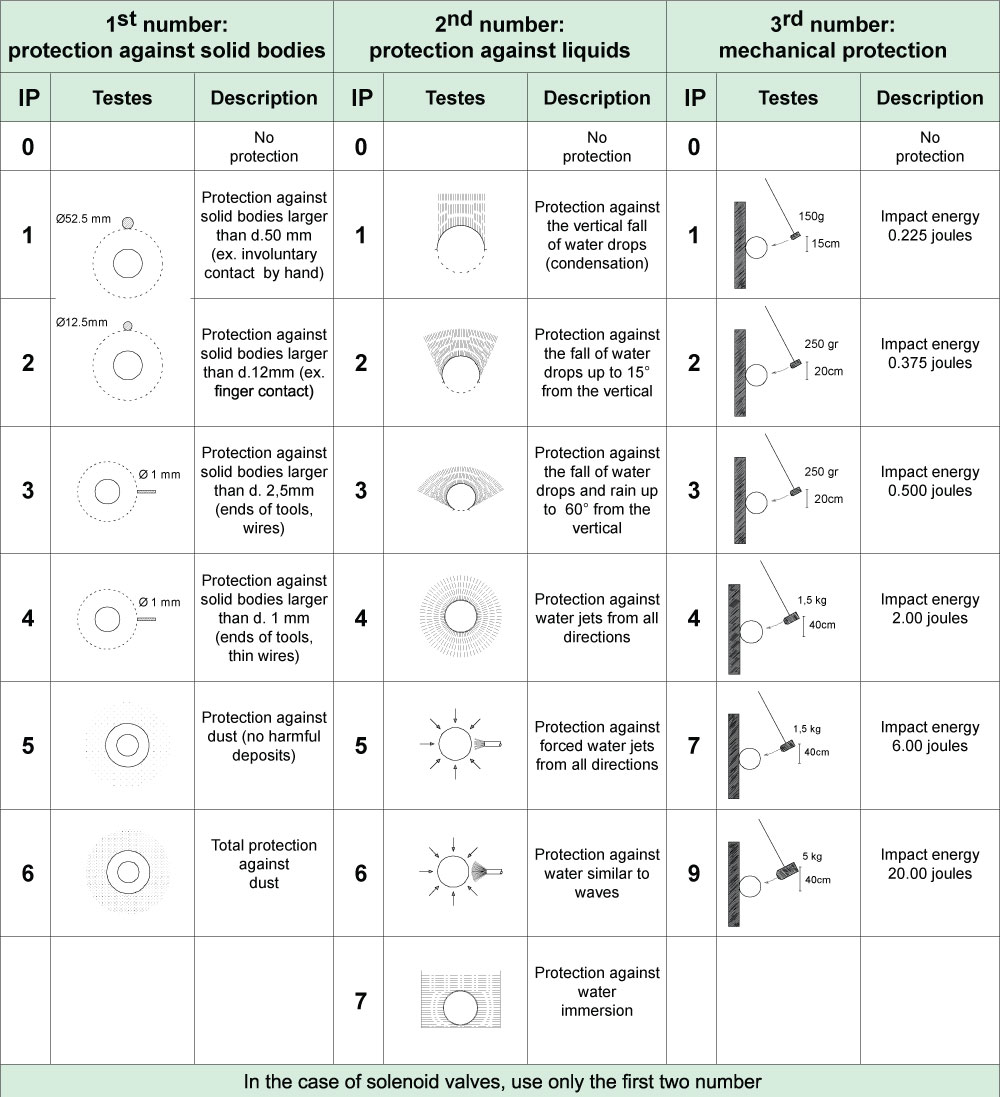
Protection class IP
Compliance with the standard DIN 40050 for the electrical protection at 1000 Volt AC and 1500 Volt DC
Insulation class according to CEI 15-26
The indicated temperature is the effective temperature of the insulation and not the overtemperature.
Insulation class | Temperature °C |
Y | 90 |
A | 105 |
E | 120 |
B | 130 |
F | 155 |
H | 180 |
200 | 200 |
220 | 220 |
250 | 250 |
Service
The coils are normally expected to be used in continuous service (ED100%).
Definition of “Continuous service”: when the electrical connection time exceed the thermal constant of the coil by approx. 1/4 .
As a general rule, the continuous service corresponds to an electrical connection time that is equal or higher than 15 minutes.
It’s possible, for non-continuous service (e.g. ED50%), either to have coils at powers that are higher than the standard ones, or to use the coils with an ambient temperature higher than the ones indicated.
ED = connection time / (connection time + disconnection time)
EXAMPLE = 5’ (connection time) / 5’(connection time) + 5’(disconnection time) x 100 = ED50%
Coils power
The power (P) indicated is referred to a temperature of 20°C. For DC current it is as follows:
P(Watt) = V(Volt) x I(Ampere) ; P= V2 (Volt) R (Ohm)
In the case of AC current, the value is referred to the apparent power during inrush (connection moment) and during holding.
P(VA)= V(Volt) x I(Ampere)
In the case of AC current, voltage and current are not in phase with each other. Phase angle between current and voltage is shown by the angle φ of the resistance triangle (the three sides represent: resistance, reac- tance and impedance of the circuit). In the case of AC current the power showed in Watt become:
P(watt) = V(Volt) x I(Ampere) x power factor φ
power factor φ = power factor is always less than 1
The power, or electric input, in a AC current solenoid valve, is higher dur- ing inrush while it decreases when the plunger’s stroke is complete. In the DC current solenoid valve, as the power depends from the coil’s Ohmic resistance, the power is the same during inrush and also when the plunger’s stroke is complete
In the international system (SI) the physical and technical units are validated as follows :
Unit of length | Meter | (symbol m) |
Unit of mass | Kilogram | (symbol Kg) |
Unit of time | Second | (symbol s) |
Unit of electrical current | Ampére | (symbol A) |
Unit of temperature | Kelvin | (symbol K) |
Unit of luminosity | Candle | (symbol cd) |
Pressure | Old messure units
Kilopond per cm² Kp/cm2
Meter of water column mH 0
Millimeter of mercury column mmHg
Metric Atmosphere at
Atmosphere atm
They were replaced in the SI from Pascal.
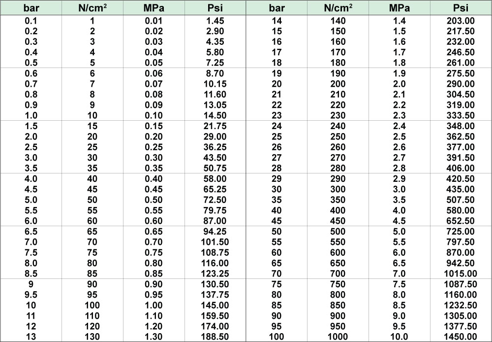
One Pascal corresponds to the pressure of 1 Newton, which is acting on the area of 1 m2. 1 Pascal=1N/1m
Unit Pa is a very low value and for standard industrial applications, the Bar (symbol bar) is used.
1 bar = 0.1 MegaPascal (symbol Mpa=1.000.000 Pa).
The conversion from the old unit of measure to the new one (SI) is the following :
1 Kp/cm² = 0.981 bar 1 bar = 1.02 Kp/cm2
The conversion in the SI unit is also possible where the metric system is not yet used.
Conversion : 1 bar = 14.50 psi | 1 psi = 0.07 bar = 7.000 Pa
Pressure values, except specific references, are referred to the atmospheric pressure
Flow calculation
Each solenoid valve has a flow coefficient (Kv).
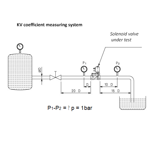
It’s possible, with this data, to calculate the flow. Given the loss of flowing pressure (pressure drop),the media type and the working pressure it’s possible to calculate the flow rate.
This flow coefficient is determined by way of experimentation according to the standard VDE 2173 and it represents the quantity of water discharged from the solenoid valve with a pressure difference of 1 bar at a temperature between 5°C and 40°C.
Liquids : Q = Kv √ ∆p/p
Gas : ∆p= ∆p < P₁/2 Qⁿ = 514 x Kv √∆p x P₂ /pⁿ x (273 + t)
∆p= ∆p > P₁/2 Qⁿ = 257 x Kv P₁ /√ pⁿ (273 + t)
Air : ∆p= ∆p < P₁/2 Qⁿ = 26 x Kv √∆p x P₂
∆p= ∆p > P₁/2 Qⁿ = Kv x P₁ x 13
Steam : ∆p= ∆p < P₁/2 G = 31,6 x Kv √∆p /V₂
∆p= ∆p > P₁/2 G = 36,1 x Kv √ P₁/V₁
Kv = | m³/h | Flow coefficient |
Q = | m³/h | Flow |
Qⁿ = | m³n/h | Flow coefficient |
P₁ = | bar | Normal flow (20°C 760mm Hg) |
P₂ = | bar | Inlet pressure |
Δp = | Bar | Pressure drop (differential pressure between inlet & outlet ) |
ρ = | Kg/dm³ | Relative density referred to water |
pⁿ = | Kg/dm³ | Normal relative density referred to air |
G = | Kg/h | Mass |
t = | °C | Inlet media temperature |
V₁ = | m3/Kg | Inlet specific volume |
V₂ = | m3/Kg | Outlet specific volume referred to “P2” |
Technical tables
Pressure
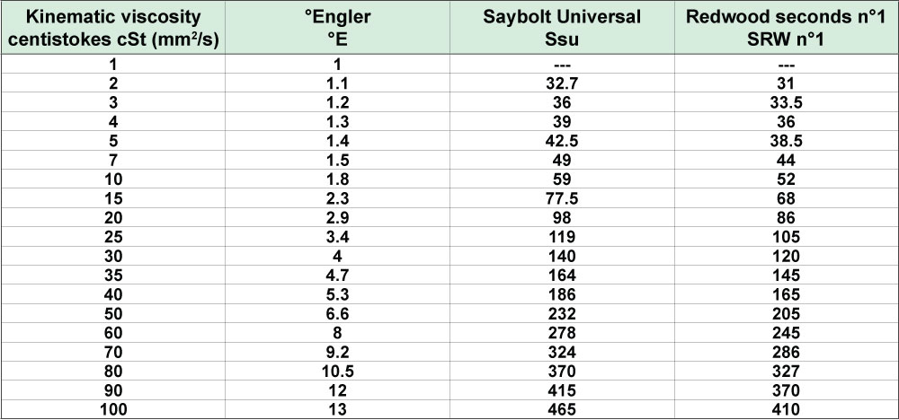
Viscosity
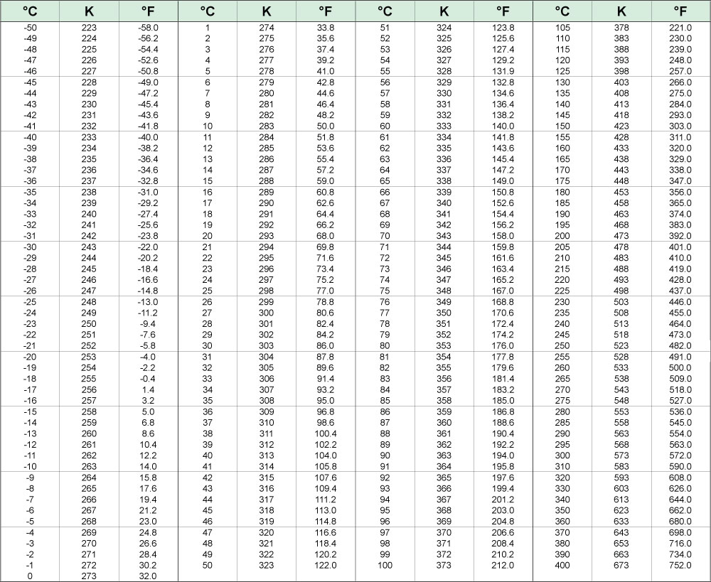
Temperature
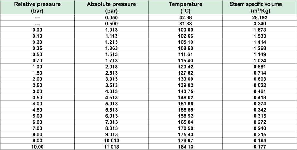
Steam
Specific gravity
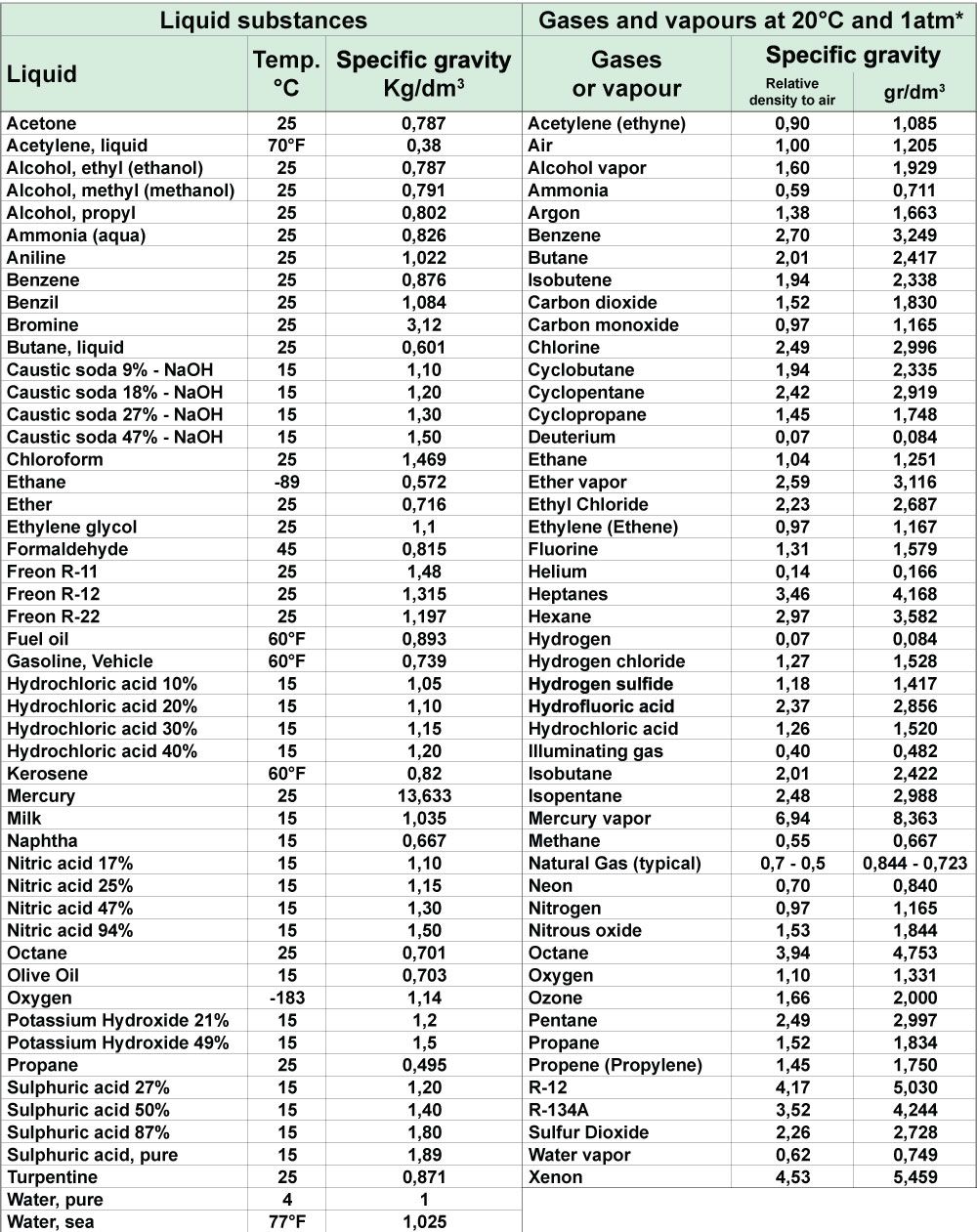
*) NTP -Normal Temperature and Pressure - is defined as air at 20°C and 1 atm
Specific gravity is the ratio between the density (mass per unit volume) ofthe actual gas and the density of air, specific gravity has no dimension. The density of air at NTP is 1.205 Kg/m³
Response time
The Response time (Rt) of a solenoid valve is the period passing be- tween the energisation (or de-energisation) of the coil and the moment when the outlet pressure reaches the 50% of its peak.
Example of a circuit test:
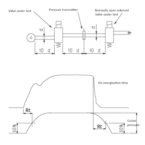
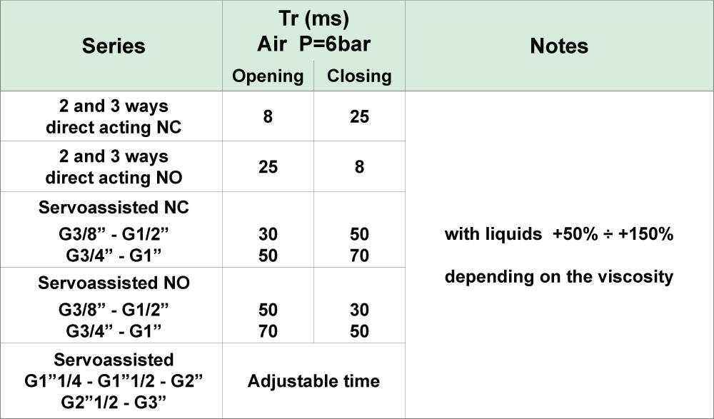
The response time depends from the type of valve, the nature of the me- dium, the pressure and the current (AC or DC), if these value are mea- sured at the moment of electrical connection or disconnection.
Tailor-made solutions
Based on the trinity of People, Customization & Technology, relieving you is the core of what aim fluid control has to offer you. If technology is second nature to us, relieving you might be our first. We call it relieving you because we offer technical, logistical and cost-saving solutions - from idea to solution & implementation - so that the continuity of your flow & fluid process remains guaranteed and / or is improved as well as your peace of mind.
Advice & Deed
From advice on complex issues to the simple ordering of (repeat) orders via our webshop, you can deploy us as a supplier of parts, assembler, product specialist, process specialist, technical adviser, engineer, product developer, project manager or total provider, depending on your needs.
The right technical, logistical and customized solutions
Solving your issues is central at all times. This concerns more than just the focus on applications, processes and products. Our multiple brand policy gives you a wide choice of products and price categories. In combination with our technical know-how and solution-oriented approach, we can deliver customized solutions in many, if not all, cases.
Call or e-mail us!
We will of course be happy to advise you on your technical and logistical support and all your customized work. Do you want to know more or do you have questions?
Then please contact us. This can be done by calling +31(0)499 49 10 90. Feel free to schedule an appointment with us by filling in the contact form.
Ekkersrijt 7310
5692 HH Son en Breugel
+31(0)499 49 10 90
info@aimfluid.nl
Stay informed of news & promotions